Automatic passenger counting systems for public transport
- Like
- Digg
- Del
- Tumblr
- VKontakte
- Buffer
- Love This
- Odnoklassniki
- Meneame
- Blogger
- Amazon
- Yahoo Mail
- Gmail
- AOL
- Newsvine
- HackerNews
- Evernote
- MySpace
- Mail.ru
- Viadeo
- Line
- Comments
- Yummly
- SMS
- Viber
- Telegram
- Subscribe
- Skype
- Facebook Messenger
- Kakao
- LiveJournal
- Yammer
- Edgar
- Fintel
- Mix
- Instapaper
- Copy Link
Posted: 15 December 2010 | Ivano Pinna, Bruno Dalla Chiara, Francesco Paolo Deflorio Transport Engineering, Politecnico Di Torino and Francois Mbarga Bessala, Industry Professional | No comments yet
This article describes and compares new technologies for the automatic counting of passengers on both rail and road vehicles, highlighting their advantages and issues, with general indications on their respective levels of outlay. It also deals with monitoring systems for weigh-in-motion, used as an indirect measurement of the passengers on-board1.
Nowadays, passenger counting operations are often developed on surveys, throughout the territory and using manual procedures: even though these may be capable of providing highly accurate values, which can be taken as a reference point in analysing the precision of the automatic systems, the manual procedures are not usually homogeneous in surveys, since they inevitably depend on the operator who performs them and may also be influenced by the time of the day – early morning versus the last hours of the day – and by a repetitive task.
On the other hand, the APC (Automatic Passenger Counting) systems, can be much more appropriate and of greater interest, as related to this short analysis. It is important to underline that – even though most of them are still at a development stage – the passenger counting technologies available on the market are various and the issues of different kinds; the combinations of technologies are such that no solution can be considered to date better than others or economically preferable a priori; every solution should be analysed in detail for applying it thereafter to the actual conditions of the public transport system or company.
This article is intended to shortly examine the different solutions of passenger counting technologies and to provide some suggestions as related to the management of data, in order to outline a general framework which may facilitate a more justifiable, customised choice of an automatic counting system.
Tools and technologies
In order to count people on buses, tramways, metros and trains, the two main following procedures can be summarised:
1. Counting independently from the ticket (for buses, tramways, trains): a. monitoring of single passengers, usually by technologies on-board the vehicle; b. monitoring of the overall load on the vehicle, with technologies applied to the suspensions/air springs or on the ground
2. Counting related to the ticket (for metros, trains), sometimes also recognised as ERF (Electronic Registering Fareboxes) solutions.
In the former case, the counting can be based either on the detection or attempted detection of the single passengers or indirectly, usually by ascertaining the weight of the vehicle under the passenger compartment or on the infrastructure, that is normally the road pavement.
As usual, the cost of the system needs to be contained, and this is related not only to the type of technology but also to the relevant hardware-software combination.
The ‘1a’ type solutions – frequently obtained by using a double sensor – can be frequently more expensive than the ‘1b’ ones; this is essentially due to the need for developing appropriate counting stations: for instance, in a 12m, 3-door bus, six sensors and two dedicated stations may be usually required.
Counting independently from the ticket has to be carried out by means of appropriate sensors, which may detect the passage of people through gates, usually the doors of buses, tramways and trains. Some manufacturers of APC technologies supply equipment which can perform such function; a widespread solution is based upon the use of infrared sensors, which act as active switches; in case of passive switches, pyrolectric sensors can be used.
In some of them, only infrared (IR) ray switches are used, in other ones, double sensors (e.g. active and pyroelectric IR) are used to enhance the reliability of the counting.
As far as this topic is concerned, the manufacturers declare accuracy in passenger counting with an error contained between 5 and 10% on the total amount of passengers which are actually present. However, the class ‘1a’ counting systems are frequently still at experimentation stage and would be worth further investigation both as related to the CAN integration and in the assessment of the counting reliability.
In the ‘1b’ cases, counting can be developed indirectly, on the basis of the load on-board or by monitoring the weight directly by means of plate sensors; a further alternative, analysed further on, is the detection of the vehicle load on the ground.
In the former case, the number of people can be detected by assuming the average weight of a person: the counting is performed by load sensors either on the ground or on the suspensions: various types are available and are nowadays experimented in other contexts as well. The main disadvantage linked to this kind of counting is the variability of the dynamic load on the shock absorbers, besides the lack of important actual field experimentation documented in the literature.
Infrared sensors
The infra-red detectors can be divided into two main categories, namely:
» Sensors of the active type, consisting of a transmitter and a receiver; they create a punctual ray and operate as on/off detection
» Sensors of the passive type, which divide the sole infra-red ray into bundles, thus creating an area of volumetric detection.
In the first case, the infra-red emitters are generally set parallel to one another so that the LED interruption occurs in the direction of crossing and the entry direction can thus be discriminated from the exit one: because of their ‘bar’ configuration, this type of infra-red sensor is also defined as ‘barrier sensors’ (see Figure 1).
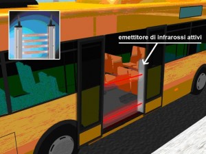

Figure 1 Example of an active infra-red emitter installed on a bus
Aweak point in this automatic counting solution – which, amongst other things, can also be easily found in commerce – is the need of installing more than one sensor per door, with a consequent cost increasing. In order to prevent the infra-red ray from being avoided by a passenger and evaluate the crossing direction, a minimum amount of two sensors is to be installed on every gate, but the number of LED’s may increase remarkably if the gates are larger than 2m.
The use of passive components generates a less punctual ray (the LED is replaced by emitters which generate ‘widened’ infra-red bundles), composed by two parallel arrays whose arrangement allows diversifying the two typologies of signal reflection, whether the passengers are entering or leaving the vehicle.
The issues relevant to the number of sensors to be utilised and – subsequently – to their cost cannot be overlooked because, as in the case of the active systems, more than one sensor per door is to be applied to detect the passage direction. As mentioned above, the electronic device used by the passive infrared-red sensors is pyroelectric (see Figure 2), i.e. it ‘reacts’ to the sudden temperature variations or – better – to the infra-red radiation emitted by a human body; this typically emits a frequency included in the range between 7 and 14 μm.
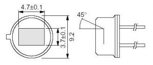

Figure 2 Example of a pyroelectric sensor
Solutions with sole passive components are often utilised to detect the motion in surveillance systems of large-sized internal or external environments; adapting them to automatic counting is not difficult, but – if the coverage bundle emitted by the sensor is too large, the counter may be erroneous.
The application of passive infra-red sensors, conceived for the sole detection of people, and which can be modified with the support of a counting device, is often rather expensive. The market provides even solutions that – in order to count the entries and exits with the greatest accuracy – use a sensor which contains both a passive and an active component.
Treadle mat sensors
Treadle mats – placed on the steps of a bus, a tram or a train – register passengers as they step on a mat. This solution relevant to the APC technologies is produced by several companies operating in the transport industry: the counting system uses treadle mats (see Figure 3) located in proximity of the vehicle gates, typically on the access steps.
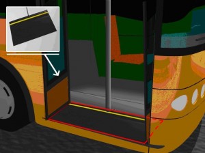

Figure 3 Example of a treadle mat installation on a bus
The metal structure can be covered by a layer of rubber and attached to the steps by means of purposely-allocated attachment structures, or simply glued by means of high seal adhesives; the latter solution is less frequently applied because it may deteriorate rather quickly.
Their installation generally does not call for special care; it must nevertheless be considered that the edge of the mat is not active, i.e. it does not commute the switch; subsequently, the position of the mat is to be studied and experimented so that the metal plate deforms every time a person transits on it, in order not to obtain wrong data due to missing detection.
If the public transport line equipped with this kind of APC is always very crowded, the errors can be relevant and – in such cases – the use of different means, such as passive IR sensors, may be preferable, or the access to the vehicle and exit from it can be managed by other instruments – such as turnstiles – to have a ‘sole line’ access to the vehicle, which enables the control system to count the passengers one-by-one.
The analysis of the weak points in this technology shows that it calls for careful installation, also in order to avoid frequent and sometimes difficult replacements, which are nevertheless far easier than in the case of infrared sensors. This requires the most accurate arrangement of the mat and a cover of the electric system, of the power supply cables and connections to the CPU, thermal insulation and the most careful location of the cables, so that no tears or breakages on either the cables or the cover rubber are caused by passengers entangled in them.
Table 1 summarises the main typologies of automatic counting systems monitoring singular passengers independently from the tickets: the treadle mats and the infra-red sensors.
Table 1: A comparison between treadle mats and infra-red systems.
|
Treadle mats
|
IR
|
| Very accurate (even over 95% in optimum conditions of use) | Generally less accurate that the treadle mats (estimated approx. 90%) |
| No preventive maintenance required | Daily cleaning of the sensors is recommended |
| Not visible to the passengers | Visible to the passengers |
| Less issues of erroneous counter activations due to foreign objects | Higher likelihood of erroneous activations |
| Easy installation also in case of large doors with the use of handrails | More difficult installation if 2 or 3 sensors are used on each door |
| Need for appropriate gates, with at least two steps | They can be virtually installed on any kind of vehicle |
| Generally more complex installation | Simpler installation with a sensor, but higher accuracy required |
| Generally more difficult replacement | Easier replacement |
| Not susceptible to electrostatic emissions | Potentially susceptible to electrostatic radiations |
| Need of slower passenger flows, possibly in “single row” | Capability of managing “faster” and more compact flows of passengers |
| Mechanical parts in movement more sensitive to dirt and environment conditions | No moving parts |
Use of load cells on suspensions of the vehicles
The weight of the vehicle can be acknowledged by locating load cells on the suspensions of the vehicle itself (see Figure 4).


Figure 4 Example of a load cell and electro-pneumatic valve (LH), to detect the load of the vehicle; example of an air spring for a bus (RH).
This technology is already used in the field of transport, since both load cells and electropneumatic valves are currently used to detect the load on the suspensions, but for reasons which are usually different from passenger counting: these devices are utilised on trains or trams to evaluate the strength required to be applied on the brakes, which depends on the weight of the vehicle.
The concern with this type of solution is the variability of the dynamic load on the suspensions or air springs, which can be overcome by measuring the load status only at the beginning or end of stops, therefore when the vehicle is at standstill.
Load and passenger detection based on the WIM systems
The WIM (Weigh In Motion) systems enable the estimation of the number of passengers on a public means through the ground loading of the vehicle detected before and after the stops, once the dead weight with driver and an estimate on the fuel in the tank are known.
The WIM systems essentially consist of sensors of different type which are introduced either directly or by means of structural steels (whose shape varies depending upon the configurations) onto the rails or in appropriate ditches machined in the carriageway and then covered.
Some main fields of application of the WIM sensors are: observation of the traffic in real time, toll applications, economic and statistic studies, studies aimed at maintenance programs, statistic environmental studies.
Therefore, the adoption of WIM detection systems enables information to be acquired on the typology of the means (load axles, overall weight, wheel track) which, mated to the more conventional ones (traffic flows, occupation rates, headways or distance between the vehicles, speed and length of the vehicles themselves) result to be essential not only for more complete information on the traffic and different flow modalities but are also functional to new strategies for the right management of the road infrastructures: maintenance, safety in circulation and reduction of the polluting agents. Within the automatic counting, it is obvious that the WIM solutions can also be integrated to the APC systems to verify the reliability of the data obtained, either in real time or scheduled in some periods of the year.
The WIM systems identify the dynamic stress due to the passage of the vehicle on the sensors and obtain – by data processing through some programs – the static load in real-time.
Knowing the weight of the vehicle at the beginning of the service, including the driver and the fuel, the average consumption and considering an average weight per person, the number of passengers on a public transport vehicle can be traced back.
A WIM detection system consists of some main components, as shown in Figure 5 and as follows:
» ‘Proximity switches’, capable of measuring flows, distances between vehicles, speed and length of the different road and/or railways vehicles
» Sensors of different typology, capable of supplying, through dedicated software, the weight per axle, the tracks of every vehicle in order to trace back the different shapes in transit
» A CPU to process and manage the information coming from the sensors and induction detectors, then store them
» Power supply units (by batteries, electrical and solar energy)
» Communication system between the different stations by modem, as GSM or GPRS
» Software package for the analysis and statistic processing of the collected data, as well as programs to ensure the quality of the measurements.
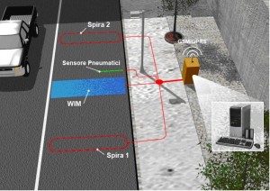

Figure 5 Example of a WIM detection station with GSM/GPRS connection
Other solutions: optical sensor and vision solutions
The optical sensors, also defined as OPS, are at development stage though in some cases have already been presented by some manufacturers. Their use is not yet diffused in the transport companies, because of their recent implementation: according to the manufacturers, they allow the same accuracy as the treadle mats, but with lower difficulties as related to both maintenance (there are no moving parts and, subsequently, the risk of dirt infiltration is lower) and installation (in case of only one sensor, as in the passive infra-red sensors).
The detection is of the optic type, i.e. they manage to detect the shapes of the passengers and distinguish them from other ones, such as animals or bags; they also detect their moving direction and subsequently identify either the entry or the exit movements.
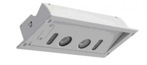

Figure 6 Example of an APC based on vision systems
As regards, the vision systems, on the market there are different solutions, but almost all are based with two stereoscopic cameras able to capture images in the area below the devices. These systems, mounted above the doors, are able to count passengers entering or leaving buses, trams or trains with a high accuracy. Those systems generally have integrated LEDs, which enable the system to operate in almost any kind of lighting condition. An adjustable counting threshold allows through measurement of passenger heights the distinction to be made between children and adults.
The great characteristic of those devices is that they are able to record time and date information which allows users to make a required statistical analyses at a later time and it is possible to verify all results at any time, through the comparison with video recordings. These systems are easily installed and, according to some constructors, offer counting accuracy greater than 98%.
Main components linked to an APC system and errors
The analyser is an essential component for the connection between sensors and servers – be they on-board or remote – of an APC system: it determines the number of passengers in in-feed and out-feed on the basis of the signals transmitted by the sensors.
As visible in Figure 7, the analyser is connected to the following essential functional units:
» Power supply (24V dc)
» Micro-control based signal processing
» Sensor interface
» Data bus interface2
» Modem for radio transmission of the data.
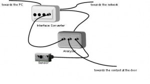

Figure 7 Data management scheme inside the means of transport
Last but not least, the significance of the appropriate electrical insulation of the analyser, cables and all the components connected to the APC system should not be overlooked, mainly in the case of passive infra-red systems, which are particularly sensitive to both the electromagnetic sensors and the heat.
In general, the analysers have one, two or four connections per sensor and either one or two connections per door contact; subsequently, an analyser can be connected to a maximum amount of two door sensors: this is an important factor to be evaluated when designing and programming the whole system. The transmission of data between analyser and sensor is regulated by a microcontroller.
It is important to keep into account the errors in passenger counting; an objective judgement in passenger counting, should consider namely:
» The error on the total number of passengers
» The error on passengers in in-feed and out-feed
» The unbalance error.
The unbalance error describes the absolute errors and – therefore – it is particularly important in comparing the different installations and the APC systems.
The field experience accrued in several years and many applications ensures the following values for the rough data (i.e. the ones considered before processing) of the passenger counting system:
» Passenger error ≤ 5%
» Passenger error in in-feed ≤ 10%
» Passenger error in out-feed ≤ 10%.
Conclusions
Passenger counting can be very useful for the management, scheduling and planning of the public transport, since it enables to set the transport service according to the observed demand, in order to improve the level of service provided to the users.
The different types of available APC systems on the market have been shortly described; the applications show that the use of technologies to detect the location of the vehicle (AVL) is nowadays consolidated and evidently necessary to integrate the information coming from the APC systems.
Finally, no technology is better than the other ones in absolute terms: the final system performance depends on the objectives (i.e., the use of the collected data), on the size of the fleet of vehicles to be monitored, on the need of integration with other technologies and programs which are perhaps already activated within the public transport company, on the numerousness and sampling frequency required, on the type of vehicles and on other factors connected to the service to be dealt with.
References
1. A more complete and technological analysis had been published in “Dalla Chiara, Deflorio, Pinna (2010), “Automatic passenger counting and vehicle load monitoring/ Rilievo automatico dei passeggeri e del carico dei veicoli, Ingegneria Ferroviaria, Ingegneria Ferroviaria – Rome, February 2010”, of which this article is a synthesis and updating.
2. IBIS (I/O Buffer Information Specification), RS-485, RS-232 o J1708, Firewire, USB, HDMI (High-Definition Multimedia Interface), Light Peak; in some cases, or on some analysers of specific design, also with other interfaces or with additional switch outputs.
3. BOYLE D.K. (1998), “Synthesis of Transit Practice 29, Passenger Counting Technologies and Procedures”, Transit Cooperative Research Program, 1998
4. PAVLIDIS I., FRITZ B., SYMOSEK P., PAPANIKOLOPOULOS N. P., MORELLAS V., SFARZO R. (1999), “Automatic Passenger Counting in the HOV Lane”, Minnesota Department of Transportation, 1999.
5. KIMPEL T.J., STRATHMAN J.G., GRIFFIN D., CALLAS S., GERHART R.L. (2003), “Automatic Passenger Counter Evaluation: Implications for National Transit Database Reporting”, presented at Transportation Research Board Annual Meeting 2003, Transportation Research Record.
6. TCRP (2003), “Uses of Archived AVL-APC Data to Improve Transit Performance and Management: Review and Potential”, Document 23 – Project H-28, Final Report prepared for: “Transit Cooperative Research Program”, TRB of the national academies, by FURTH P.G., HEMILY B. J., MULLER T.H.J., STRATHMAN J.G.; June 2003.
7. DALLA CHIARA B., DEFLORIO F.P., PINNA I. (2010), “Automatic passenger counting and vehicle load monitoring / Rilievo automatico dei passeggeri e del carico dei veicoli”, Ingegneria Ferroviaria, vol. LXV, ISSN: 0020-0956. N. 2, pp. 101-138, Rome, CIFI Ed., February 2010
Related topics
Business Models, Fleet Management & Maintenance, Intelligent Transport Systems (ITS), Multimodality, Passenger Experience, Public Transport, Ticketing & Payments, Transport Governance & Policy
Issue
Issue 6 2010
Related organisations
Politecnico Di Torino
Related people
Bruno dalla Chiara, Ivano Pinna


