Artificial Ground Freezing
- Like
- Digg
- Del
- Tumblr
- VKontakte
- Buffer
- Love This
- Odnoklassniki
- Meneame
- Blogger
- Amazon
- Yahoo Mail
- Gmail
- AOL
- Newsvine
- HackerNews
- Evernote
- MySpace
- Mail.ru
- Viadeo
- Line
- Comments
- Yummly
- SMS
- Viber
- Telegram
- Subscribe
- Skype
- Facebook Messenger
- Kakao
- LiveJournal
- Yammer
- Edgar
- Fintel
- Mix
- Instapaper
- Copy Link
Posted: 6 December 2006 | Dave Hindle, Director, OtB Engineering | No comments yet
The need to cool the environment in mass transit underground railways is becoming increasingly urgent, particularly in older networks where rising temperatures place an additional strain on systems that were never designed to cope with increasing passenger numbers. This article looks at one potential solution for cooling the deep Tube network by Artificial Ground Freezing.
Introduction
Most of London’s deep Tube network was constructed during the early 20th century with even more recent lines (such as the Victoria Line built in the 1960s and the Jubilee Line a decade or so later) built with similar specifications in terms of tunnel dimensions and ventilation. Only the most recent Jubilee Line Extension (JLE) meets modern day standards and even this relies on train sizes originally specified for the line.
The need to cool the environment in mass transit underground railways is becoming increasingly urgent, particularly in older networks where rising temperatures place an additional strain on systems that were never designed to cope with increasing passenger numbers. This article looks at one potential solution for cooling the deep Tube network by Artificial Ground Freezing. Introduction Most of London’s deep Tube network was constructed during the early 20th century with even more recent lines (such as the Victoria Line built in the 1960s and the Jubilee Line a decade or so later) built with similar specifications in terms of tunnel dimensions and ventilation. Only the most recent Jubilee Line Extension (JLE) meets modern day standards and even this relies on train sizes originally specified for the line.
The need to cool the environment in mass transit underground railways is becoming increasingly urgent, particularly in older networks where rising temperatures place an additional strain on systems that were never designed to cope with increasing passenger numbers. This article looks at one potential solution for cooling the deep Tube network by Artificial Ground Freezing.
Introduction
Most of London’s deep Tube network was constructed during the early 20th century with even more recent lines (such as the Victoria Line built in the 1960s and the Jubilee Line a decade or so later) built with similar specifications in terms of tunnel dimensions and ventilation. Only the most recent Jubilee Line Extension (JLE) meets modern day standards and even this relies on train sizes originally specified for the line.
The problem of poor ventilation and need for cooling is most acute in the deep tube lines, where labyrinthine stations with small diameter platform and concourse tunnels are linked by even smaller and tortuous pedestrian footways. Only the main escalator tunnels provide a reasonable degree of openness, which is often not extended to the ticket halls they serve. The running tunnels themselves are generally of minimum dimensions to allow the passage of the tube stock (which itself is among the smallest in the world) except over specific sections such as crossovers and step-plate junctions where an increased tunnel diameter is required.
These confined spaces, where air movements are largely reliant on the piston effect of the passage of the trains themselves, are also the location of numerous sources of heat including:
- electrical cables, both high (traction) and low voltage (power)
- train motors, transmissions, bearings, brakes and interior lighting
- platform and concourse lighting and signage
- escalator and travolator motors, bearings
- the passengers and staff themselves.
The resultant heat build-up has been taking place over many decades with the effect that the actual fabric of the underground together with the surrounding strata to a depth of about 10 metres has absorbed heat to near saturation point. Consequently, the ground can no longer provide any heat sink or cooling effect and can actually radiate heat back into the environment.Temperatures in excess of 40oC are not unknown, particularly during the night-time closure in the summer months when warm air is drawn in from outside during the day and stagnates in the tunnels at night. Recent increases in passenger utilisation of the Tube network have caused the problem of overheating in crowded trains and stations in the summer months to approach unacceptable proportions, resulting in increased incidents of heat-stress and complaints.
Transport for London (TfL) are currently evaluating a proposal to cool the Tube using groundwater and trials of the system are planned in 2007. In parallel with this, Private Public Partnership (PPP) operator Metronet have commissioned OtB Engineering to develop a quite different approach to the problem using Artificial Ground Freezing or AGF.
Existing deep Tube ventilation and cooling
The only significant means by which London’s underground deep tube railway network is ventilated and cooled is by the piston effect of the trains running through the tunnels. The deep Tube network currently has about 120 tunnel cooling fans whose prime purpose is to remove heat from the tunnels when the trains are not running at night. Depending on how the fans were designed they may be either supplying fresh air into the system or extracting hot air. Typically, each fan has a volumetric capacity of between 15 to 50m3. Most are between 10 to 50 years old and approximately 80% operate in extraction mode. Other than new fans installed on recently constructed sections of the deep Tube network, none have the capacity to effectively control the flow of air, smoke and heat in an emergency situation.
Operating in parallel with the fan system is a draught relief system, which usually comprises a shaft (typically with a cross-sectional area of 15m2), connected to the running tunnels by louvered ventilation panels close to the head wall at the train entrance to the platform tunnels. The purpose of the draught relief system is to help reduce the piston effect of the trains before the train reaches the station. Air is also drawn down and in through the draught relief system as the train leaves the station. Up to 150m3/s of air can be moved with every train movement between stations. As a train approaches and passes through a station, air is dispersed through the station cross-passages, corridors and escalator shafts. The draught relief system, train velocity and tunnel cross-sections are sized to limit air velocities to an acceptable level (usually well below 7m/s).
The scheme
It is clearly impracticable to provide a complete conventional air conditioning system for the deep Tube network that is able to operate cost effectively the whole year round, nor is it particularly needed to operate at peak performance except for a relatively short period during the summer months or during an emergency. In essence, the solution proposed is in the notion of a thermal storage battery that is able to sustain a required day-to-day and year-to-year performance profile without the need to introduce and dispose of large volumes of coolant waste material such as water or ice into an already constricted underground environment. For this purpose the system utilises the well-established technology of Artificial Ground Freezing (AGF) directed at the ubiquitous water-bearing chalk strata and granular sediments lying well below the deep Tube network.
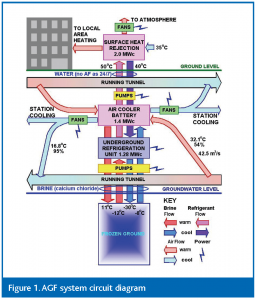
The cooling system operates entirely as a closed loop (see Figure 1) that delivers a substantial, rapid and sustainable injection of cold air into the tunnel ahead of an oncoming train that would push it en-mass into the station areas whilst at the same time allowing it to enter and cool down the interior of the train. Multiple train passes would effectively inject the passenger areas with cooled air, which would tend to remain in the lower underground passenger circulation areas dissipating progressively to the remainder of the system. The locations for such injection ports ideally would be between the closely spaced stations within the central and deepest parts of the Tube network.
The surface expression of the work would be limited and could be incorporated into existing structures and utilities, with much of the underground work restricted as much as possible to the existing way-leave of the tube network. The first AGF systems would be installed in the hottest part of the underground network, probably in the central city area, with further AGF plants added progressively to form a cooling network or grid radiating outwards to build a complete cooled underground environment that has an inherent sustainable stability.
The Artificial Ground Freezing (AGF) process
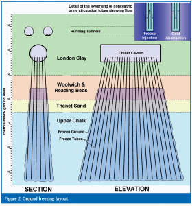
The AGF would be installed entirely from underground openings constructed in the London Clay off-line from the live railway and the ground freeze will take place mainly in the Upper Chalk aquifer, extending through the overlying water-saturated Thanet Sands and the lower portion of the Woolwich and Reading Beds, which are essentially granular in composition and highly permeable. The London Clay itself would require protection from the AGF to avoid problems of heave (see Figure 2)
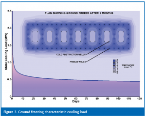
The AGF is compartmentalised by closely spaced freeze wells surrounding the entire block of frozen ground and dividing it across its width into a number of freeze-cells. Within each cell fewer, more widely spaced, cold-abstraction wells would be installed together with monitoring wells and pressure relief holes. The coolant in the form of calcium chloride brine is delivered to the AGF ‘store’ via concentric, closed-end tubes at a flow temperature of -30oC, reducing the temperature of the store rapidly until after only 2 months or so closure of the freeze block is complete in the upper strata (see Figure 3), with complete freezing of the entire block after about 6 months when the store could begin to be utilised for cooling the Tube via the cold abstraction wells to underground air cooler coil batteries at a flow temperature of -12oC. Waste heat from the refrigeration process would be rejected to surface heat exchangers where it could be utilised for local area heating.
Once frozen, the freeze would be maintained indefinitely with no part of the block being allowed to thaw, except very locally and to allow for well lining replacement, which is expected to be required only very infrequently. Temperatures within the AGF block would be drawn-down over a number of years to -25oC or lower, although individual cells would operate at a range of temperatures depending on the demand profile. During the winter months for example, cold may be being abstracted from only one cell whilst the others are being cooled. As temperatures in the tube network begin to rise in the spring more freeze-cells can be brought into operation with some remaining in reserve to cope with excessive peak and emergency demand. In this way the AGF would have sufficient flexibility to cope adequately with the wide variations in demand profiles envisaged, as well as containing a sufficient reserve margin.
Meeting the cooling load requirements
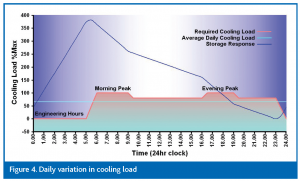
Cooling loads having been established based on the criteria of achieving an average platform temperature of 29°C and relative humidity of 40%. London Underground’s daily cooling requirements are at a peak during the morning and evening rush hours and at a minimum during the hours between midnight and 5am (see Figure 4). This profile gives an average cooling (CLG) load at about 65% of the maximum. Superimposed is the storage required to maintain control when running a cooling system continuously for 24 hours at the average load. As can be seen the storage builds during the night-time closure of the railway when cooling demand is almost zero to a peak at the start of the morning rush hour when it falls off during the remainder of the day until demand exceeds storage input during the evening peak. From that point on the store is being depleted to maintain the average cooling load requirement until it can recover from about midnight beginning the cycle again.
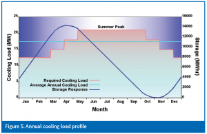
This can be extrapolated to all areas of the deep Tube network summarising the overall cooling demand over an entire year (see Figure 5). As with the daily cooling load/storage response cycle there is superimposed an annual cycle. During the winter months storage builds to a peak around the middle of April and is depleted throughout the summer months until late October when storage begins to recover again.
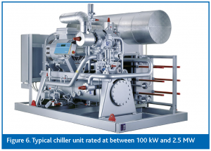
The storage required to provide cooling energy can, therefore, be adapted using these concepts to provide a flexible supply according to demand both on a daily and yearly basis. Since the system is designed to operate at a constant year-round cooling load input to the AGF store, the equipment used can be rated at its maximum efficiency without need for back-up. Since the store is so massive, it will provide an adequate margin to allow complete shut-down for a major overhaul of the chiller unit (see Figure 6) and ancillary equipment to take place without thawing out. Reliability of the system is also very high with typical chiller units being guaranteed for maintenance-free operation under these conditions of up to 10 years.
Delivering cold air to the Tube network
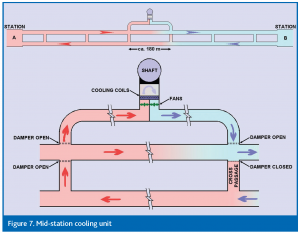
As shown diagrammatically on Figure 1 the return flow from the cold abstraction wells will pass through batteries of cooling coils over which the hot air from both the stations and running tunnels will be drawn and returned cooled by forced ventilation and the piston effect of train movements through the tunnels. The primary location for the cold air injection would be mid-way between stations where the AGF installation would also probably be located and may serve more than one Tube line. Using the access shaft for the chiller cavern and surface heat rejection pipework, tunnels are driven to intersect a running tunnel at two adjacent cross passage locations.
A bank of cooling coils and axial-flow fans are installed in the main cross-passage to draw air out of the running tunnels and return it cooled in the direction of the train movements. Control of the airflow direction is maintained by dampers fitted to the intersections of the cross-passages with the running tunnels. Figure 7 shows the situation at start-up of the system before the continual passage of trains has completely dispersed the cold air throughout both running tunnels and into the station platforms.
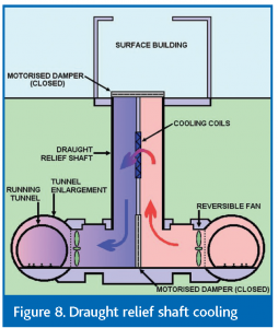
Another possibility is to utilise the existing draught relief shafts located at the ends of the station platforms. These large open shafts provide an opportunity to install a bank of cooling coils into a forced ventilated air stream by partitioning the shaft and providing dampers to control the air flow (see Figure 8). During normal train movements the fans would not operate and the motorised dampers would remain open allowing full draught relief to take place. However, at night the dampers are closed and the cooling circuit is turned on, boosting the cooling effect in readiness for the morning peak. It may also be possible to operate the system during or between train movements over the hottest period of the summer.
A significant side-effect of the air cooling would be dehumidification, which will result in condensation and frost build-up around the coils. Whilst this will be very beneficial in improving the underground environment the coils will require frequent defrosting. For this purpose some of the waste heat from the AGF process can readily be utilised.
Conclusion
This approach to cooling the Tube is not without precedent. Underground Thermal Energy Storage (UTES) projects are operating in a number of countries and are the subject of an international collaboration under the Energy Conservation Through Energy Storage Implementing Agreement of the International Energy Agency (IEA). An emerging branch of this technology is Low-Temperature UTES and in their 2006 to 2010 strategy plan the IEA cites Sustainable Cooling with Thermal Energy Storage as having been approved for further development. Canada has already adopted a national standard that will encourage the use of underground thermal energy storage for earth energy systems and are, together with countries including: Holland, Sweden, Norway, Switzerland, Germany, Austria and the US, considering or actually installing LT-UTES schemes for heating and cooling on a large scale.
The application of tried and tested technologies of Artificial Ground Freezing and cooled air forced ventilation lends itself to solving a problem on the scale of cooling the deep Tube network in London, meeting the aims set out by the IEA as a sustainable use of underground thermal energy storage. The system could be adapted for use on other similarly heat-affected metros around the world and could provide spin-off benefits in the form of the distribution of excess heat and cold to the surface urban environment, thereby offsetting carbon emissions from other sources needed to provide these commodities.
As part of their PPP remit Metronet is committed to providing innovation to the London Underground network and this initiative represents one of many such schemes to improve one of the World’s greatest city transport systems.








Issue
Issue 4 2006
Related modes
Metro


